
As we have heard for a long time, the promise is here of having a true “system on a chip.” The system has grown remarkably large of late with scads of processor cores, large caches for each, different and multiple I/O links, massive bandwidth to equally massive amounts of memory; you get the idea. But, no matter how large the chip – or our capability to cool it – the system we want to put on that chip always turns out to be bigger.
And as impressive as those processor cores may be, the processor design engineers know a simple truth: the greater the real estate consumed by each core, the fewer the number of cores possible on that chip. They also want the circuitry used in each core to be that which is used a lot. That, after all, is the basis of Reduced Instruction Set Computing, or RISC, designs. Processor cores should only support those relatively primitive operations that are most frequently used in programs.
But the engineers also know that they can design circuitry to support much more complex functions and have them execute very much faster than can be done in software using the more primitive instructions in the typical processor architecture. These faster and more complex operations could be added to processor cores as instructions in their own right, but – once replicated over many cores – might not fit in the chip.
Of course, I’m not telling you anything new here. You already know that the solution to adding more hardware, more times than not, is to develop chips which provide faster circuitry for the needed function and hang those chips as an I/O device from the point of view of the processor chip. Because of this, many engineers have labored hard and long to develop really fast links to those also fast chips.
So, here we are with new functions built from really fast circuitry, hardware links with extraordinary bandwidth, and then software gets involved to drive this otherwise incredibly fast hardware. Although not always the case, often enough this software overhead simply gets in the way of fully experiencing the real benefits of this specialized hardware. We are not talking about sloppy programmers here either; this code gets tuned. The impedance, though, just does not match. The architectural requirements on the code that wants to drive this specialized hardware doesn’t necessarily match up with how this hardware wants to be driven; it takes noticeable execution time to match these up.
This impedance matching is largely the purpose of IBM Power8’s Coherent Accelerator Processor Interface (CAPI) architecture. And that is the purpose of this article, to allow you to get a sense of that what makes CAPI different, to see why it is that IBM is tooting this particular horn, and perhaps suggest where related system architectures might be going in the future.
To do that, we need first to provide some background for comparison, breaking it down into bite-sized pieces, and then do some comparative anatomy. Please bear with us; it will all make sense shortly. And then you’ll wonder what took them so long.
First, The Ideal. . . Plus Address Translation
You’ve got yourself a screamingly fast I/O-attached accelerator and you want to tell it to do something. Said differently, what you want is to ask some service to quickly execute some function, to quickly accept – and understand – some input data, and to return some data result in a format that we can quickly use.
So, what – today – is the fastest way of doing that? Via multi-threaded processing; Thread A asks Thread B – Thread B acting as an accelerator, but still executing on a core – to provide some service. Perhaps this is obvious, we’ve been using this technique for a while, but sometimes we miss the beauty of the trees for the forest. So, why is it fast?
Thread A creates an object and wants to share it with Thread B. With both threads belonging to the same process, all that Thread A needs to do is pass the object’s address to Thread B (or multiple such Thread Bs) and kick starts Thread B to execute. Done and done. Fast, clean; all that remains is some processing, some address translation, and some cache fills and related cache coherency. It does not matter what processor(s) are being used by the thread, the address value means the same thing, a reference to the same object.
It is worth also noting that, because the threads understand the same addressing model, Thread B easily understands the organization of any data being passed to it by Thread A. As an example, a linked list – or any more complex object having many internal data references – can be fully understood as is by Thread B even if created by Thread A. Straightforward and fast. Programming-wise, completely natural and easy to work with.
As some preview context, what we will be describing next – here using inter-thread data sharing on Power8 processors to drive the point – has a strong relationship to similar sharing possible via CAPI. Since we are talking about Power8’s CAPI in order to help explain we’ll be using that processor architecture’s – the Power Architecture’s – naming conventions.
The address that these two threads are sharing is called an Effective Address (an “EA”). It is normally scoped only to the process shared by these threads; the EA is typically a process-local address. Another process using the same values for an address is typically referencing completely different data. Effective Addresses are what the program code knows as an address; it could address
- heap storage, or
- some data in each thread’s stack, or
- the program’s instruction streams, and
- a lot more storage types.
Again, for inter-thread data sharing, all that is needed for rapid sharing is for two threads to share the same Effective Address.
Although some computer science texts imply otherwise, an Effective Address is not an address into physical memory. Said differently, the typical programmer using an EA does not know – and for data security, system integrity, and virtualization reasons should not know – where the data really resides in physical memory. Instead, the address of the shared object in physical memory (e.g., DRAM) is called a Real Address (RA) in the Power architecture; more on that in a moment. Most programmers do not use Real Addresses, they use Effective Addresses. What we’re alluding to here is that, in order for the hardware proper to access the shared object, the object’s Effective Address – and all EAs within that object – must be translated by the processor core’s hardware to a Real Address. It is the Real Address that is used by hardware to actually access memory. To do so, at the time that each thread is switched onto a processor, enough state is loaded onto that processor for this address translation hardware to know what to do. Keep this last in mind as we start getting back to CAPI.
It happens, though, that the process-local Effective Address is not normally translated directly to a Real Address in the Power architecture. Instead, the process-local EA is first translated to an OS-global Virtual Address (VA). Each process provides to the processor hardware the capability by which this is done; this capability – this state – is similarly provided to the processor when the thread becomes active on that processor. Each process provides its own addressing context.
With the address translation state known to each processor, given a program’s EA, the processor then knows how to translate Effective Addresses (EA) to Virtual Addresses (VA) to Real Addresses (RA); when this is successful, the processor hardware is then capable of accessing the object in physical memory.
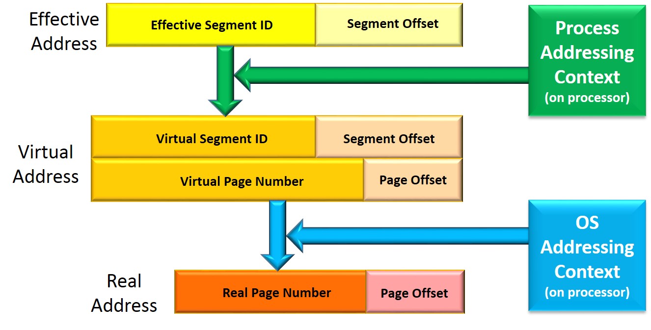
Once the processor has the RA, the remainder of the process of object access is just memory or cache accesses and cache coherency. This last part is complex, perhaps, but variations on this address translation is what the processor is doing with each and every memory access. It has to be fast. Every access – data or instruction stream – translates an EA and then accesses memory/cache. Once set up, it is very fast. And it is very frequent. And that is what we are trying to drive home with this section; once you have an address and the capability and rights to use it, no matter which processor, the access is fast, very fast.
Keep in mind, by the way, that we are saying this to provide context for CAPI.
Again, data sharing between threads in the same process is enabled by nothing more than sharing the same Effective Address. Data sharing between threads of different processes is only slightly more complex. In this case, Thread A of Process A creates an Object A and refers to it via its process-local Effective Address EAA. Using a protocol securely moderated by the operating system, a Thread B of different Process B can be given the right by Process A to access an Object A. With the completion of that protocol, the OS provides to Process B an Effective Address EAB, but one still referencing Object A. The process-local Effective Address values used for EAA and EAB (both referencing Object A) are typically different values. So, since they are different, how does the expected sharing of Object A work? What typically happens on the Power architecture is that EAA and EAB are mapped to the same OS-global Virtual Address VAA; this single VA is (and was) used by Process A to access Object A. The common VAA translates to a common RAA where the object really resides in memory.
So, using the common VAA, the remainder of the address translation finds the shared object at RAA for both threads in the process. (Alternatively, different Virtual Addresses – VAA and VAB, rather than just VAA – could also have been used, with both translated to a common Real Address RAA. The Virtual Addresses are “aliases” when both can be translated to the same Real Address.) Such inter-process sharing is slightly more expensive, yes, but once set up, the common object can be repeatedly accessed using the Effective Address(s) of each process to the object and be as fast as was the case for intra-process sharing.
The processor(s) are told (at task switch time) the context of the Effective Address being used, but, once known, sharing the object is fast. Interestingly, this data sharing does involve some data copying – this done at the cache level – but the program code is kept completely unaware of it. As seen shortly, CAPI extends upon this concept.
I/O-Based Sharing. . . Plus Address Translation
OK, after all that, let’s recall that we are really intending to talk about I/O-based accelerators. In the previous section, the “accelerator” was just another thread (or two or three or more), but all executing on generic processor cores. As noted at the beginning of this article, the typical place to hang a performance-enhancing accelerator is as an I/O device. Nothing special here, it has been done for forever. But let’s, in this section, take a look at what it takes to drive such a device and from there get a sense of some of the performance trade-offs.
Different Address Spaces
In the previous section we wrote of the Power processor’s ability to quickly translate Effective Addresses (EAs) into Real Addresses (RAs), and from there to access memory. But the I/O device – your accelerator hung as an I/O device – also needs to access the same object in memory as the processors, but the I/O device does not share that capability; it does not understand nor have any idea how to handle EAs. You – your program – wants to share an object with the accelerator and knows the object’s location object via an EA, but passing that EA to the accelerator would be fruitless. That address (that EA), though, happens to be the only way by which you know the object’s location. We have a bit of a quandary.
The object, though, really does exist in Real Address space. Perhaps it also spans or – as a complex object – resides partially in multiple real pages found all over memory. Some I/O devices are allowed to use such Real Addresses; we’ll assume that here for simplicity. [Others devices use a separate I/O address space model that must be separately translated to Real Addresses through a completely different address translation process. This may exist for reasons of system integrity and security. Please realize that this requirement adds additional processing time over what we’ll be describing next.] To talk to such an accelerator, we provide it the object’s Real Address(es). It happens that doing so is not quite that easy.
Starting with the object’s EA, the processor hardware can quickly translate Effective to Real Addresses. The same address translation done in software, in preparation for the I/O operations, takes considerably longer. For system security/integrity reasons, this manual translation software must also be part of a trusted OS (or in virtualize-able systems, by a trusted hypervisor). These software steps, for the Power architecture, include:
- Finding the objects describing the current Process and, in there, its EA translation tables, then searching there to provide the corresponding VA.
- Find the OS’ page table, and search there for the VA page(s), providing from there the Real Address page(s). Since your object might span or reside in multiple pages, this is done for each page. (This step is often executed below the OS by a trusted hypervisor.)
It’s not like this takes forever, but it does take measurable time and it is done frequently, for each operation and each page. This entire process, though, simply provides only the object’s Real Address. That is only part of the process of doing I/O. We’re not to the data yet.
Pinning/Unpinning Memory
For your program’s code running on a processor, whether or not your object is actually in physical memory is typically irrelevant. If the object is there, the processor can access it. If not, the OS is told and transparently pulls it into memory on your behalf. Your program uses the object’s Effective Address and the object gets found; this is all transparent to your program; the programmer needn’t even be aware.
That, though, is because you are using an Effective Address. Pity the poor I/O device, using only Real Addresses. When the I/O device gets around to accessing your object, is it still in memory? The accelerator could use a Real Address of your object, but is your object still at that physical location when the access actually begins? Of course, I/O has worked well for years, but the reason it does is that – prior to the I/O operation proper – something in the OS has ensured that your Effective/Virtual addressed pages remain at their Real Address while the I/O operation is executing. That takes time; it’s called pinning memory. When the I/O operation completes, the OS must unpin this same memory. This is done for each page being accessed. Again, time.
Complex Objects
We’ve been speaking in terms of an “object” being made available to an I/O-attached accelerator. For the object-oriented programmers amongst us, you know that such objects are not necessarily contiguous blocks of memory. Such objects are often rather complex, made up of many references. As a simple example, picture an otherwise simple linked list; each node of the list addresses – via an EA – the next node. Each one of those many “references” are Effective Addresses.
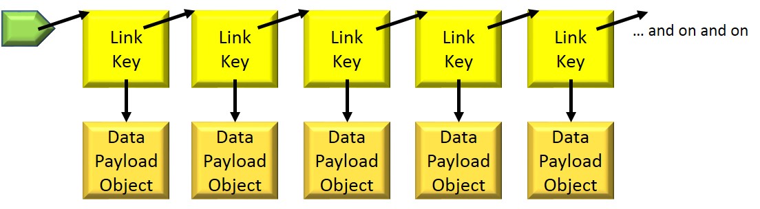
So here we are, wanting to pass such a complex object consisting of Effective Addresses to an accelerator, an accelerator which has no way of understanding or translating those same Effective Addresses. So, instead, in order for the accelerator to efficiently access your object, you are forced to reorganize the contents of the object into a format that the I/O-attached accelerator can understand. Unfortunate.
Such is life before CAPI.
Recap
So far in this story. We have shown that
- Two threads, one providing the other an object’s EA, can very quickly share access to that object. The only real delay during access is the time to pull the object into the associated processor’s cache(s). The second thread can be thought of, from the point of view of the first (the requesting) thread, as a core-based accelerator, a not unreasonable approach.
- An I/O-attached accelerator might be able to access the contents of memory with roughly the same latency as a processor, but there is some considerable software latency required to give it both the right and the opportunity to do so. And then there is additional performance cost to remove that right. Since the beginning of time, it has been sufficient to continue speeding the accelerator and decreasing its latency to memory. Now this software overhead is appearing as a significant contributor to the processing time.
Once we’ve given the accelerator the ability to work with the object, your program kick starts the accelerator and then, perhaps, sits back for a while until the operation is complete.
CAPI. . . Plus Address Translation
We previously wrote of threads being used as accelerators, arranging for one or more server threads to take over one or more cores. A client thread efficiently passed them some objects’ EAs, these threads took over some cores, and used the capabilities found in the typical modern processor to complete our work.
An accelerator, though, is not necessarily a typical modern processor. Instead, we’ve suggested it is specialized circuitry which may or may not be driven through its paces by its own set of instructions. In any case, it’s intended to do it faster.
To use it, you create an operation request with parameters, pass it to the accelerator, take over the accelerator for a moment; when complete, a subsequent operation can take over the same accelerator. At some level, it feels a lot like assigning a Thread to a core; the accelerator is not necessarily executing the same sorts of instructions as a core, but it sure feels like it is executing on behalf of a client thread.
To get even closer to this notion of a thread “on an accelerator,” you have seen that that accelerator needs to support the same addressing model as that of a processor core. We want to be able to pass a complex object via an Effective Address, with the object itself built using Effective Addresses, and have that accelerator understand.
Oh, and by the way, all of the memory operations executed by the accelerator, both reads and writes, we want these to be consistent with the cached contents of data residing in the processor core’s caches.
The above description of wants is the essence of the CAPI architecture. CAPI is a description of what such an accelerator – and the interface hardware on the processor chip – needs to do to support those requirements. What it enables is not the typical processor core, but instead an accelerator, an accelerator which can handle Effective Addresses and cache coherency and units of execution in a manner similar a core, in a manner consistent with the addressing model expected by most programs.
So, how? Back to processor cores to explain. When you start up a thread, you are also telling that thread where – at what EA – to find its instructions for driving its work. But, implicitly – a capability set up by the OS – you are also telling the thread how to tell the processor how to translate the thread’s EA. Roughly the same thing is done when driving the CAPI-based device. The “thread” – the function request – is not addressing some instruction stream, but it is providing the accelerator a function request sufficient to allow it to do its job; the request is based on the accelerator’s specific architecture. The “thread” is also provided parameters, as would be the case in a processor core-based thread. In both, the parameters could include EAs of the objects and buffers to be used by the accelerator’s operation.
The thread description – the functional request with parameters – could be queued up (i.e., similar to threads waiting their turn on a processor), and when next the accelerator becomes available, it processes the work as directed by the “thread”. Upon completion, the “thread” would be placed by the accelerator into a completion queue.
A Side Note On CAPI’s Addressing
There is another similarity as well. The reason that processor cores can translate EAs-VAs to RAs consistently quickly is that the processor cores maintain internally a set of address translation caches. For VA-to-RA translation, the Power architecture and others call this translation cache a Translation Lookaside Buffer (TLB); we will use that term here. This cache, inside of each core proper, contains the VA-to-RA mappings of the most recently used sets of virtual pages. But what most folks don’t know is that every core’s TLB is kept consistent with the current VA-to-RA mappings maintained by the OS/hypervisor. Each TLB is just a cache of the contents of a much larger structure – we’ll call it a “page table” – representing the address mappings of far more pages; when this structure’s contents changes, the TLBs much be forced to follow suit, and follow suit on all cores.
As the page table changes, all core’s TLBs must follow suit. At any moment, one core might be changing the page table, but every core is watching for it to broadcast requests describing the change; these requests are typically mapping invalidation requests. Once again, when an arbitrary core changes the page table, it broadcasts this fact to all of the other cores in the SMP. Recall again that these cores can do very rapid address translation because of their TLB. Since we are also talking about CAPI devices, devices which also want to rapidly translate addresses, the broadcast is also to any device which might be sharing the same VA-to-RA mappings. But this process is not done yet. In order to maintain consistency, every core, every device must respond to the core doing the broadcast before the broadcaster continues execution. This can take a while, with the broadcaster waiting, so each core must respond as quickly as it can. If the CAPI device maintains a TLB-like cache – and it might if it does repeated accesses from the same page(s) – it needs to play along. Partly because of I/O paging operations, partly because of associated page aging algorithms, such TLB maintenance can be frequent.
Pretty esoteric, right? But it is CAPI’s similarity to processor cores that helps it avoid much of the overhead.
The First CAPI Device?
As far as I can tell, the first device slated to use CAPI is one being called the Data Engine for NoSQL. At a very high level, the essence of this is the support of a two-tier memory topology. The NoSQL in this case happens to be a largely in-memory data structure server supported by Redis running on a Power8-based system. The two tiers happen to be
- The Power8’s DRAM with up to 1 TB per processor chip.
- Up to 40 TB of flash memory using the IBM FlashSystem 840 storage.
What’s the big deal, right? It’s just a bunch of solid-state drives (SSDs) acting as a persistent memory subsystem hung off a generic SMP. Well, actually, this CAPI-based does seem to be a big deal. That’s easy enough to say, of course, but let’s do some comparative anatomy to help show this point.
As some of you folks know, we’ve had two-tier memory for a lot of years. For the rest of you, picture it like this: Suppose that some complex application’s data working set is larger than the amount of first-tier memory (DRAM) available to it. The data was already fully addressable by that application’s process(es) – something made easier by 64-bit addressing – but that otherwise addressable data could not fit in the DRAM; so where does it go? Your application is likely unaware, because the OS attempts to transparently keep the excess working set out on some persistent-storage I/O devices like hard disk drives (HDDs) or – more recently – solid-state drives (SDDs). The first tier is the DRAM, the second is the HDD/SDD, the latter as attached I/O drives. These devices may or may not be completely separate from that used to hold your files. (For a more complete overview of this notion, see Wikipedia’s Paging.)
Of course, there is a performance impact for doing this; any time that your application’s data is not currently in the DRAM, close to the processor, the OS must spend the time to find the otherwise addressable data out on an I/O device. This takes time, quite noticeable time. More frequently accessed data tends to stay in memory, but when relatively frequently accessed data is also being found on HDDs, performance suffers. Of late, this performance issue has been getting offset by having still faster SDDs, but your application is still suffering from the time to simply make the I/O access, even from these relatively faster devices.
The basic problem is that the DRAM available for your application was just not large enough, and very possibly could not be made large enough. What your application wants to frequently access can’t fit and the OS provides this slower alternative. Fine, standard stuff, really. We provide this as background for the reason for this first CAPI device which we’ll get to shortly.
IT folks are, though, if anything, definitively innovative. If one system’s memory is not enough, they say, let’s hang together a lot of systems, each having their own DRAM, and spread our application and its working set of data across all of these system’s DRAM and processors. These multiple systems supporting the one application tend to be called a cluster. Oh, and by the way, system pricing is such that we can hang a lot of these together at a cost cheaper than comparable large single systems. Great idea. And, as long as one system infrequently needs the data residing on another, it works really well. This, too, is a form – a more recent form – of two-tier memory; hopefully, when that part of an application running on one system needs data, it can find it in DRAM local – the first tier – to that system’s processors. Otherwise, as the second tier, the application’s data may be found in the DRAM of another COMM-linked system of the cluster. Fine, the data is in memory – in DRAM – either way and so should be quickly accessible. Even better than SSDs, right? And, further, the inter-system communications links are hyper fast so even the data residing in a remote system DRAM can be accessed quickly, right? Well, yes, until you factor in the overhead of simply asking for and then handling the data receipt of the data you needed (not to mention handling the protocol to coherently manage changing the data as well). This, too, takes a while, and, if frequent enough, really shows up as a major component of the application’s performance.
OK, got it. So what makes this CAPI-based solution of two-tier memory so good? Take a look at the following figure which attempts to show this solution. Again, at some level, this looks a lot like a generic SSD-attached, two-tier memory solution, but it’s more than that.
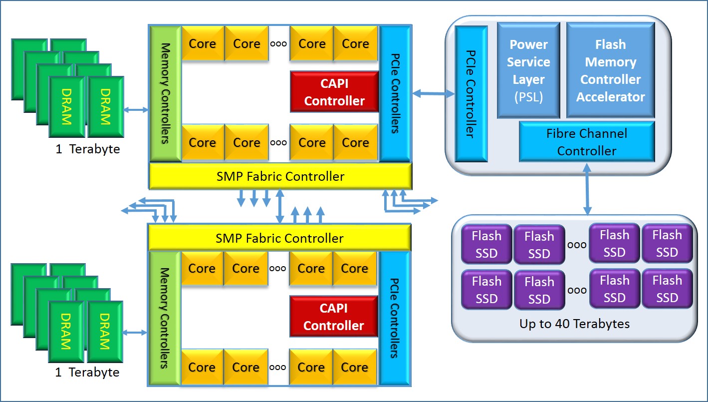
In this device, however, the CAPI-based device providing the interface between the processor’s SMP and the SSD knows all about the Effective and Virtual Addressing used by the application running on this SMP. That CAPI device can access the objects and pages of this SMP in the same way as the processors do. Yes, the device needs to communicate over an extra link – PCIe, at first – than do the processors, but aside from that it has the same rights and capabilities – but only as much – as the processors relative to accessing the SMP’s data.
As a result, yes, it does look like a generic second-tier storage I/O device, but it is also considerably faster. Again, big deal we all say. Well, yes, we respond, but the penalty for not finding needed data in first-tier memory is also many times less, at least according to IBM and Redis. They go on and say that, as a result of this rapid access, the 40 Terabyte second-tier memory has a way of making the couple/few terabytes of SMP DRAM perform as though it were multiple times larger. They add that this perceived increased size might, for many applications currently using the distributed memory of clusters, completely offset the benefits – and the need – of such large-memory clusters, both from a performance and a system’s management and programming effort point of view.
In some still unsupported future for this, if you want more DRAM, you add more NUMA nodes; Power8 has up to 16 of them. You want more persistent second-tier memory, you add more of these devices; each Power8 chip supports a CAPI link.
Push Me, Pull You, Or Maybe Blurred Lines?
And now for something completely different. . . .
So, CAPI seems to allow what is otherwise just another I/O device
- to efficiently – using high-level addressing – access the memory of an SMP,
- to maintain cache coherency with the cores of that SMP while doing so, and
- to stay consistent with the current virtual-to-real address mapping.
Although it is not necessarily executing instructions like the SMP’s cores, that CAPI-based device is sort of, kinda, maybe acting like another core in that SMP. It’s not, of course. It is an accelerator hung on an I/O link. But it can also access the SMP’s memory and interpret data structures like a core. So what is it? Is the fact that this accelerator is hung on an I/O link rather than the SMP fabric relevant?
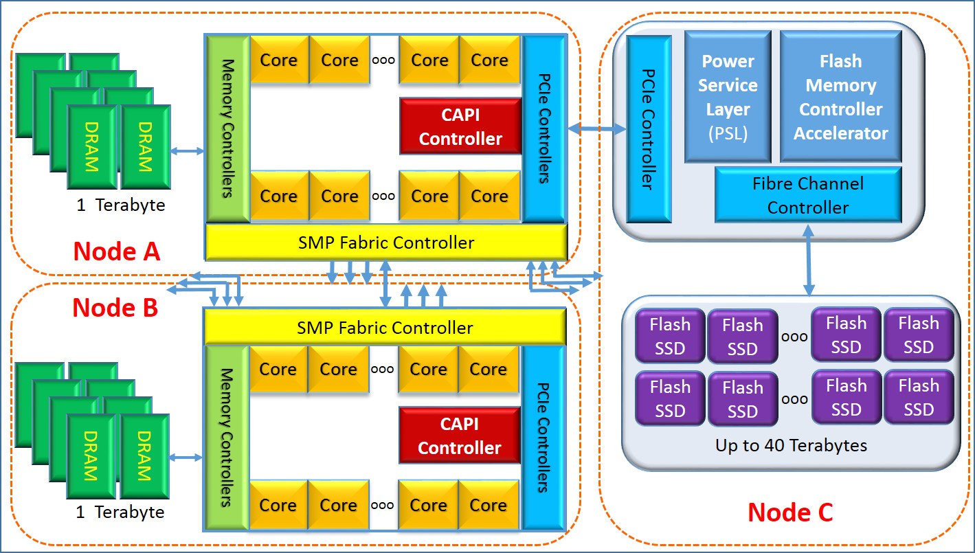
Let’s take another look at that last point by subtly redrawing the previous figure and adding a red box around each “node”. We see that each “node” has some processing capability and some notion of local memory. We also know that, using the same addressing we’ve been discussing
- the cores of Node B can access the memory and cache of Node A,
- the cores of Node A can access the memory and cache of Node B,
- the CAPI device – Node C – can access the memory and cache of both Node A and B, and
- the SMP fabric helps maintains a consistent state of the data throughout all of the caches and memory.
So far we’ve been talking about the memory and cache associated with the SMPs. The Real Address space we’ve been translating to is that which addresses the memory of Nodes A and B (and all similarly attached nodes) only. Each byte in the memory of Nodes A and B in total is represented by a unique real address and that type of address is used by the cores of Node A and B and by the CAPI device to access that memory. What is symmetric when we are looking only at the nodes of the NUMA SMP looks more one-sided when we include the CAPI device.
But notice that this CAPI device is capable of accessing its own local “memory”; every byte of the SSDs also has some unique physical address. Perhaps that’s all that is necessary for this first CAPI device. But in some future, if the CAPI device can access the SMP’s memory, can the SMP’s cores access some CAPI device’s memory?
We have no idea what IBM’s – or perhaps the OpenPower Foundation’s – future plans are for CAPI, but it’s worth observing that the Power architecture already has some precedent to enable the symmetry. The Power architecture has a notion of Memory-Mapped IO (MMIO). The processor can generate, typically via EA address translation, a type of real address used to address “memory” outside of its own DRAM. MMIO is used to access into the “registers” and “memory” of I/O devices. With this CAPI device pictured above, the Power processors would perceive byte-addressable SSD memory as being within this MMIO address space. That, though, requires the processors to support a huge Real Address space over and above what is required for its own memory; everywhere that an RA shows up – such as in every core’s TLB – the hardware needs to support enough bits to handle this full Real Address space.
We have also overlooked a really important point. Not only can the cores of Nodes A and B access and change each other’s memory, but when doing so, these accesses remain consistent throughout all of their core’s caches. If a core on Node A changes a block of data in its own cache, Node B core’s cache can’t be allowed to continue to see and change an old version of that same data block. The SMP’s fabric helps ensure this; software is not involved. So now picture Node A core’s cache holding data from the CAPI device’s memory. If the CAPI device subsequently changes that data block in it own memory, would the hardware be capable of telling Node A’s core(s)? If not, unlike the SMP, the cache(s) are not remaining coherent.
Yup, a bit esoteric again. But the issues to bring CAPI about can be rather subtle as well. Still, not only has CAPI introduced a means of rapid data access by what is essentially an I/O device, but CAPI seems to have blurred the boundary between what separates cache-coherent SMPs from I/O-based accelerators. It will be interesting to see where this approaches goes in the future.
After degrees in physics and electrical engineering, a number of pre-PowerPC processor development projects, a short stint in Japan on IBM’s first Japanese personal computer, a tour through the OS/400 and IBM i operating system, compiler, and cluster development, and a rather long stay in Power Systems performance that allowed him to play with architecture and performance at a lot of levels – all told about 35 years and a lot of development processes with IBM – Mark Funk entered academia to teach computer science. He is currently professor of computer science at Winona State University. And, having spent far and away most of his career in the Rochester, Minnesota area, he continues that now working in IT for a major medical institution that is also located there.

Hello Mark
Excellent article. Hope the readers will grasp the full value of what a technology like CAPI provides for I/O adapters like FPGA’s, GPU’s, Networking and the fibre card used with the IBM FlashSystem for the Redis Labs NoSQL solution called IBM Data Engine for NoSQL.
Looked for your email to send this to you directly but didn’t see it listed anywhere. There are two mistakes. Redis Labs is the company and the product. That is what is used with the IBM Data Engine for NoSQL. There is a open source edition called just ‘Redis’. The Redis Labs product is significantly more scalable and feature rich. Also, the IBM FlashSystem 840 storage uses Flash Modules and not SSD’s. SSD’s are essentially a form factor like a disk drive usually with a SAS adapter connecting to a SAS bus, etc. The Flash Modules look like DRAM or memory DIMMs. Just bigger / longer. They are hot swappable in the 840 just like a SSD is in competing models. Also, the FS840 was just replaced with the FS900. This is simply the latest generation of the product with more capacity. I hear it is wrapping up testing/validation and will be announced any day if it hasn’t already as an upgrade to the FS840. It will offer more RAID protected capacity but otherwise perform the same.
Thanks. I am glad you enjoyed it. I rather enjoyed researching and writing it as well.
And thank you for the corrections. You are, of course, correct on the terminology.
Great article. As optimization is the last leg to get most performance out of any platform, having a Uniform Addressable Scheme (UAS) across devices is a good candidate.
If only normal consumers can try these system innovations at a reasonable price point.
Thank you very much for putting all this information together in such a well-written article!