

Scanning through Power10’s detailed announcement material, I’ve seen a lot architecturally that intrigues an avid reader of The Next Platform like myself, but one item – one that IBM calls “Memory Inception” and IBM-based techie material calls enablement for a “memory cluster” – really caught my eye. It has the feel of a diamond-in-the-rough, but over time and with some software-architecture polish you’ll be seeing it soon enough as the polished diamond that it is. It’s also one of those areas where I – teaching computer architecture as a retirement job – would gladly spend a couple/few weeks expounding on for my students. Maybe it will take that, but I’ll try to get the high points described in this deep dive as quickly as possible.
So, where to start. At its most primitive it is a Power10 core capable of accessing up to 2 PB of physical memory like DRAM. Ho, hum? Keep reading. Let’s start with observing that that laptop in front of you has roughly 8 GB of DRAM. In comparison, Power9-based systems support up to 64 TB; that’s massive in its own right, also over 8,000X larger than in your laptop. And 2 PB? 32 times larger than that. Yeah, you might need it someday, right?
But it’s not really its size that is the key here. This 2 PB can be spread over the memory of multiple systems in IBM’s memory cluster, and all of it directly accessible from a Power10 core within any one of them. And that memory need not be just DRAM (i.e., fails when power turned off), it can also be persistent memory. OK, with you indulgence, here I need to slow down a bit and build up from what you know. Afterall, what the heck is a “memory cluster”?
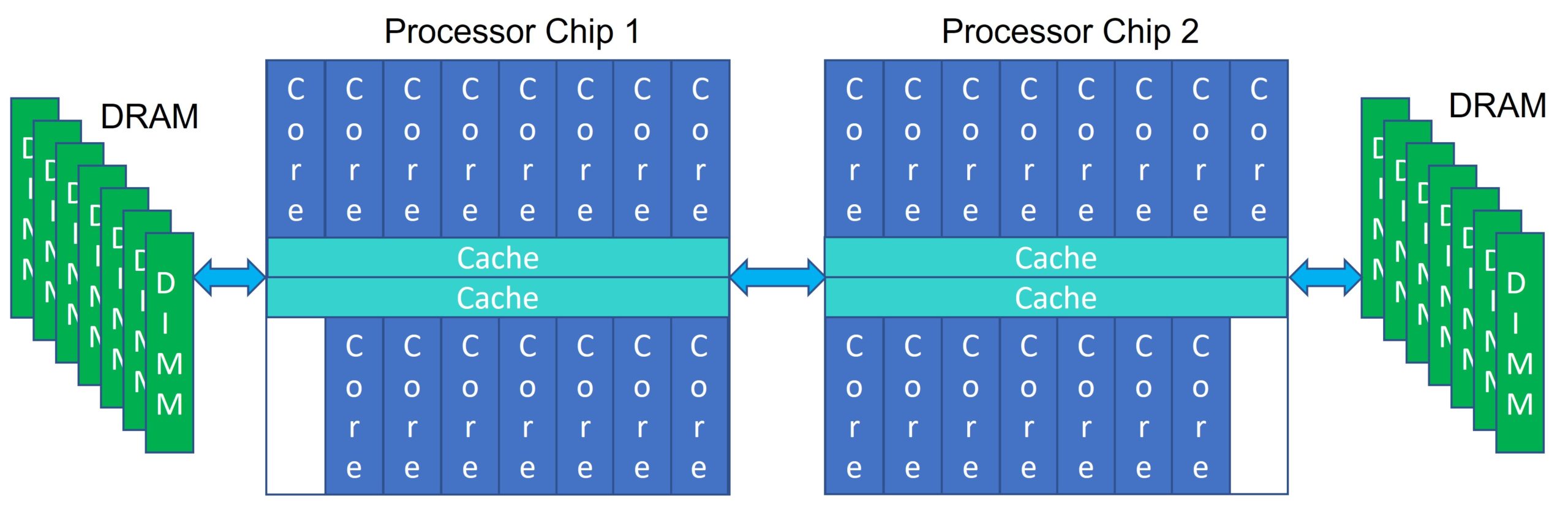
In what you normally think of as a processor system, it does not matter on which of the processors you are executing code at the moment; your application can be running on any of those cores and can access its data found anywhere in that system’s memory. Or consider this simplified two-chip Power10 system. No matter the core on either chip, no matter the DIMM hung off of either chip, any portion of memory is accessible and cache-coherent from any core. Any core’s cache can also contain memory from any DIMM (any DRAM) in that system. With an operating system spanning this entire system, no program need be aware of this topology. A core accessing only memory attached to that chip and cache residing on that chip can be faster, but that is a completely different issue; all memory and the contents of any cache is accessible from any core. You might know this as an SMP (Symmetric Multi-Processor). Power10 is capable of maintaining this normal expectation all the way up to a 16-chip (i.e., 16-socket) system.
Let’s throw in a variation, not of hardware but of how you are using it, via virtualization. If you are at all familiar with virtualization you know that you can ask that 2-chip system above to have most any number of operating systems. Rather than getting into a long discussion of how Power systems support virtualization, let’s make this simple and assign cores and memory in a near trivial fashion.
You expect Operating System 1 to have no rights to access the memory owned by Operating System 2 and visa versa. That is a limitation on the OS, not of the hardware. From a hardware core point of view, any core could still access any of this memory, but the trusted hypervisor code says “Nope.” It’s accessible, just not allowed. The hypervisor limits each OS to addresses used in accessing only local memory in this example. (Of course, in general virtualization, this addressing is far more flexible than this.) But, again, bottom line, two or more OSes, each are normally allowed to access only their own memory, even though far more is physically accessible.
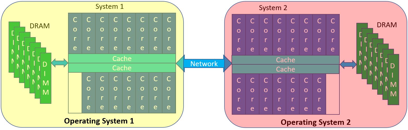
Let’s now move these two OSes to two separate but networked systems. Because of networking hardware, the only way that these systems share data is by network-based copying from the memory of one system to another, with each OS securely controlling where in its memory the incoming data gets placed. In such networked systems, a core in one system has no physical way of directly accessing the memory of another system. At least yet. Instead, in networking, a core tells a network device adapter (like PCIe), “Hey, there is some data in that particular block of data in my memory. Could you go read it from there and shove it into some memory of a target system, one that they control?” And well before that, at a much higher software level, a Process on System 1 says “Hey, I have this data buffer whose contents I want to send to another Process on System 2” to kick start the whole thing. That entire path, software and hardware, takes time.
Stepping back, that whole process of using the internet to copy data between systems appears to happen so fast to us today that we don’t even think about the time, compute, and networking capacity being used to make it happen. But it does take time and capacity, and we always have reasons to make it faster. As you are going to be seeing, Power10’s Memory Inception is a major first step in taking a big cut big into that overhead.
Did you see the difference between network-based copying initiated by a core and separately a core just itself reaching into “remote” memory? In even a 16-socket Power10 system, all memory is accessible by the load/store instructions executing on any core, no matter behind what socket that memory resides. The same thing cannot be said of – say – 16 network-linked systems all with a single socket; memory is completely disjoint and the only way to share data is through data copying via networking, even if physically right next to each other. Seems obvious enough, right, but you’d be surprised how often that distinction gets overlooked in marketing when comparing compute capacity. Either way it is just a bunch of processors, each with their own memory, right? Nope.
Believe it or not, we are making our way back to explaining Power10’s “Memory Inception” (a.k.a., memory clusters) along with its 2 PB memory accessibility.
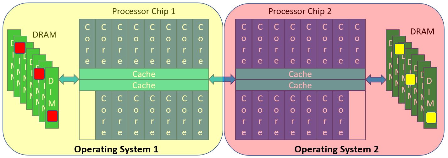
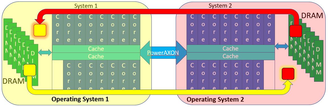
Before getting there, another quick mental image. Back to the single 2-chip system virtualized to support two OSes. Recall that normally, even though cores could access any memory, Operating System 1 is normally not allowed access into the memory owned by Operating System 2. Normally. But why not? Suppose OS 1 and OS 2 securely opened up some windows into their memory for sharing with the other operating system. (No, virtualization does not allow you to do this today.) Notice the red and yellow blocks representing those windows. A load/store instruction executing on a core of Chip 1 or on Chip 2 can access any of this memory. All that we’ve done is given those cores the right to use the address of some here “remote” memory. Both OSes can access into these windows, and it’s all done securely and only into those windows.
Again, this figure is what you have come to think of as a single cache-coherent system, an SMP. All memory is accessible by all processors and done so in a cache-coherent manner. “What you have come to think of as a single cache-coherent system” even if it is – say – 16 (or N) sockets, all with their own memory. Why? Because the hardware connecting these chips is capable of representing a request for a read or a write of a block of data in the DRAM – and transparently into the processor caches – anywhere in this entire system.
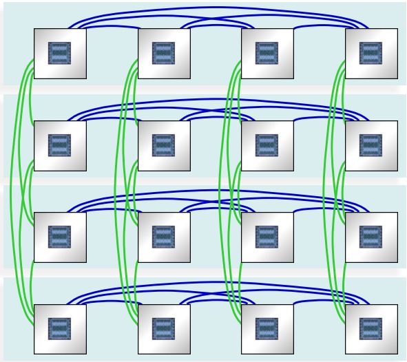
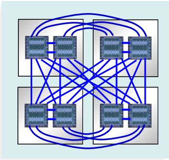
Below, stolen from IBM’s Power10 chart deck, are two such systems, on the left is a 16-chip/16-socket system (240 cores), the right an 8-chip/4-socket, each socket with memory not shown in both. Notice in particular the blue/green links – called PowerAXON – with architecture supporting the data block transfers to/from the cores and the full cache coherency. These links connect sockets both within and across drawers containing these sockets. And, of course, it is blindingly faster with massive bandwidth (32 GT/sec with total chip bandwidth of 1 TB/s). But, especially crossing drawers, these rather look like a clustered set of networked systems doesn’t it? Blindingly fast, with massive bandwidth, transporting packets of data between what you, if networked, would think of as systems. But this is not networked; this is a cache-coherent SMP. It’s the links architecture. Get the feel of this, and this from only the 1,000-foot level?
It happens that, in Power10, the same link being used between these sockets, both intra- and inter-drawer, is the link being used to create the memory cluster. The memory cluster grows on top of these SMPs via this same type of link. But, what you are going to be seeing in following sections of this article is that its architecture includes some tricks, a means of translating addresses to allow another system’s memory to look as though it is stacked on top of your own systems memory. As best I can figure, a variation of this game is something that we also saw in HPE’s apparently experimental The Machine. In The Machine, each node had local DRAM, addressable only by the local node and then addressability to massive remote memory, sections of which were owned by each node.
From William Starke, IBM distinguished engineer and a Power10 architect: “You’re able to kind of trick a system into thinking that memory in another system belongs to this system. It isn’t like traditional [techniques] and doing an RDMA over InfiniBand to get access to people’s memory. This is programs running on my computer [that] can do load-store-access directly, coherently. They use their caches [to] play with memory as if it’s in my system, even if it’s bridged by a cable over to another system. If we’re using short-reach cabling, we can actually do this with only 50-to-100 nanoseconds of additional latency. We’re not talking adding a microsecond or something like you might have over and RDMA.”
“HP came out with their big thing a few years ago. They called it The Machine and it was going to be their way of revolutionizing things largely by disaggregating memory. Intel you’ve seen from their charts talking about their Rack Scale architectures [that] they’re evolving toward. Well, this is IBM’s version of this and we have it today, in silicon. We are announcing we are able to take things outside of the system and aggregate the multiple systems together to directly share memory”. Yours truly wrote fondly on HPE’s The Machine a few years back in a series of articles on The Next Platform. More on that relationship to Power10 later.
Addressing’s Part In Computer Architecture
OK, time for some more background before going on, here on computer Addressing architecture. As I tell my Computer Architecture students, computer addressing is one of the most important and at the same time least understood concepts in computer science. Its basics have been around like forever, but at the same time – as we will be seeing here with Power10 – it is also still evolving. Addressing is also a key component of an integrated security solution; most students don’t get exposed to it enough, but that’s a subject for a whole ‘nuther article.
So, getting started. Have you ever noticed that your laptop has a lot of work going on, on it even now while you are using this browser? All that is happily running on your system, all completely isolated from every other piece of work, all unaware of and secure from any other. Each of those pieces of work (a.k.a., a program) is called a Process. Each Process has their own private address space, one which the Power architecture calls an Effective Address, a space which is 264 bytes in size. That’s 16 giga-gigabytes of space, one for each and every program running on a Power-based system, and far larger than the amount of physical memory in any system. Effective Addresses are the type of address being used by these programs and programmers. Those programs know diddly squat about addressing physical memory (e.g., your DRAM), making these process-scoped Effective Addresses location independent. The actual location of your data in physical memory could be anywhere. It works great and it’s been like that since about the beginning of time.
But, of course, you do access data in the DRAM. A combination of hardware, operating system, and – in virtualized systems – the hypervisor, all map portions of each Process’ Effective Address space ultimately onto Real Addresses, addresses which more closely represent the location of data in physical memory. There is a unique Real Address for every byte in your system’s memory. Please keep this last in mind. And, again, within any OS there can be scads of Processes, all competing for their data to reside in physical memory; if their data doesn’t reside in memory the processors can’t access it at that time. To drive this point home, picture all of these Processes, all running concurrently, each capable of accessing 264 bytes (16 giga-gigabytes), all needing their data to fit in the 8 gigabytes of the DRAM in your laptop. And somehow it works great.
Effective Addresses are location independent, but certainly scoped to each Process, each typically limited in scope within an OS instance. Interesting to me as a CS instructor, most programmers tend to be divorced from even this notion of an address. For most programmer it is “objects”, location independent, organization unaware, just a block of memory upon which object-based operations are executed. For such, does it matter where these objects are and how they are accessed? Remote objects are just as fine as local, especially if both use the same type of addressing as any other object and very nearly as fast. The object exists, it is in memory somewhere, my program currently running on a processor can get to it quickly and muck with the object using my object reference (i.e., an Effective Address). All is good.
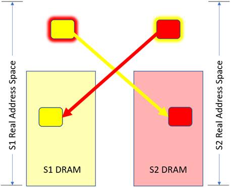
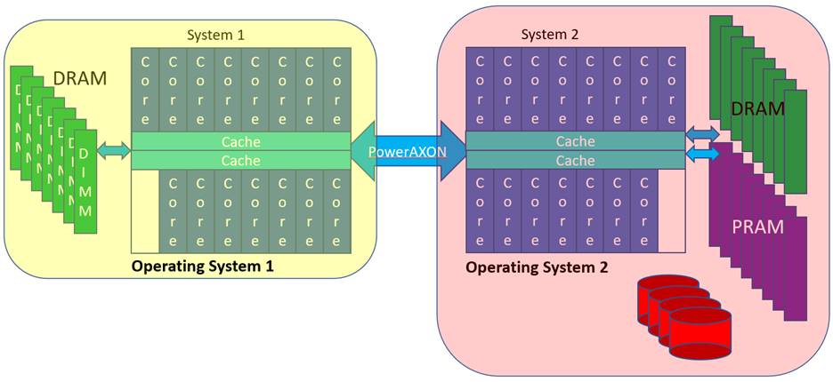
So, as objects, suppose that we have two Processes 1 and 2, one in each of the systems – System 1 and 2 – shown below. Let’s have these Processes need to very rapidly communicate. Let’s have each Process – again one per system – create an object in its own Effective Address space, essentially just an array of bytes. Nothing special so far. We are going to use these buffers for communications between the Processes, and since IBM calls this concept Memory Inception, let me call each such object an “Inception Object”; both Processes are going to be aware of both objects. As part of the objects’ construction, a buffer of that size – let’s make it a megabyte each – gets created by each operating system in its own memory. That’s a standard operation for any object. We’ll do that here as a yellow object and a red object. See the similarly colored blocks within each system’s DIMMs below. But, as Inception Objects, these objects are going to have visibility by both Processes, even though these Processes are also on different systems. That is new and normally not allowed. The means of doing so much also be done securely. The yellow object, say at its construction says “I – in Process 1/System 1 – want my yellow megabyte object to be created and then be made visible to Process 2 in System 2.” Similarly, Process 2 wants its red object to be visible to Process 1, using the same mechanism. Visibility is enabled by having each system add a megabyte as new space to its own Real Address space and then having the PowerAXON hardware map that new local Real Addressed megabyte to its actual location in the other system. (Yes, I know, mind bending. I will be explaining this in multiple ways.) Once that linkage is set up, Process 2 then requests of its OS “Here are my credentials, may I have access to the yellow object (on System 1)?” By doing so, Process 2 gets in its own Effective Address segment ultimately mapped onto the yellow object in memory. Same effect for Process 1 wanting access to the red object. System 1’s Real Address space – the red-outlined yellow block on the left – does not have the data, it merely addresses the data which really reside in System 2. Process 1 then has its Effective Address space mapped onto this local Real Address representing this remote red object. With that Effective Address, each Process can now access the object in the remote system.
Maybe if I explain that a bit differently? Suppose a Process 1 on System 1 wants access to the red object on System 2’s memory. To get access, a rather complex but secure protocol needs to have created a new Real Address in the address space of System 1 (the red-outlined yellow block) and arrange to have that address mapped in the PowerAXON hardware to link to the red object in System 2’s memory. Because of that mapping in PowerAXON hardware, any Process in System 1 could potentially access this object. But, like any Process in System 1, the only way that it is allowed to access that physical memory is if – here – Operating System 1 provides an Effective Address range mapping onto the object’s local real address range, here the red-outlined yellow block. When that object’s Effective Address gets used in a load/store instruction by your program, the access of the red object occurs. Well, take my word for it, it works, and securely, allowing access to remote memory about as fast as for a similar access in local memory.
Process 1 and 2, so address mapped, executing on a core in its OS, now has simple and secure load/store access to any part of either object. Your program touches it as you would any object and in not too much more time your processor’s cache delivers that data to you. And all this about as fast as you possibly can with any object. No I/O involved, at least in the sense that you have understood.
Or consider this, from still a different point of view, referring to the following figure, recall that Power10 supports a 2 Petabyte (251) Real Address space. Within any single Real Address space the whole of any one system’s DRAM (at least) must reside. But this DRAM is a small fraction of the whole – say 64 Terabytes (246) – in size of the possible 251. The Power10 cores and the links can address so much more, the 2 Petabytes. So, if System 1 wants to allow access to DRAM in System 2, System 1 adds a region – a window – to its own Real Address space to locally represent physical memory in System 2. The cores of System 1 use that local Real Address, but the PowerAXON hardware knows it really represents physical DRAM in System 2. Once an Effective Address is mapped onto a local Real Address, the remote memory can be accessed and securely by your program.
 On The Subject Of Cache

I can imagine that most of you easily know the term SMP (Symmetric Multi-Processor). From my point of view, these things haven’t really been symmetric for decades, at least since they started putting multiple cores in a chip and hung those chips together to make a single system. Nonetheless, whether two chips in a socket or sixteen sockets, Power10 systems are very much still SMPs.
But, whether now with Power10 and its memory cluster support or even its CAPI support, IBM has been blurring the lines of what makes a single system also for years. And, no, IBM is not alone. So, a little bit of definition – to the best of my ability – would seem to be in order before I go on.
With SMP, here is My definition: All processors can access all memory and cache is transparent to the software. You’ve seen from the previous section that Power10’s stretches the first part of that definition with their memory cluster support; “all memory” includes physical memory on another system. And, as to the second part of the definition, if you folks know of the subtleties involved with storage ordering, you might know that in some special cases the cache is not really completely transparent to the software either. Still, I think you’ll agree with me that, expect for maybe performance optimization, most programmers are not even remotely aware of processor caches and that is intentional.
So, SMP = transparent cache. Even so, instead of building up to it, let me be right up front; within the “system” – a memory cluster – cache is not transparent in the same way it is in an SMP. Cache still gets used, yes, but software will need to be aware of its existence, still at the same time only in a limited way. Yes, I do need to explain, and that is what is coming up next.
So, explaining, we start with the basic load and store instructions executing on a processor.
- A load instruction … Accessing part of an object in memory for subsequent processing.
- A store instruction … Returning calculated results to memory.
Whether the object accessed is local and within the SMP’s memory or remote (in the sense of a memory cluster) and within another SMP’s memory, the load/store instruction know nothing about local or remote memory; using an Effective Address it says, go access memory represented by this address. Each uses an Effective Address to address their object, and ultimately the location of the object in memory is found and it is accessed. It happens, though, that each core’s execution of load/store instructions doesn’t typically access local or remote DRAM; the core accesses the processor’s cache. For example, a load instruction accessing a 4-byte integer doesn’t get that integer directly out of the DRAM; the core executing that load gets those four bytes out of a cache line in its cache. If that integer is not yet in the cache, cache management hardware asks for a block of storage – typically here 128 bytes – which contains that integer, and the core waits. Often, that 128-byte block is the unit of storage read from or written back to the DRAM. Subsequent instructions accessing from within that block find their data close by the core from within their cache and so accessed quickly. One access, one 128-byte block, subsequent accesses to/from the cache done fast.
Again, it does not matter whether cluster remote or SMP local, the cache manager used that blocks local real address to access it. If remote, as part of this process, the PowerAXON hardware uses that local real address as the first part of the process of accessing the remote memory, an access then using the remote SMP’s real address as we saw in the previous section.
Before going on, more background now on the subject of cache coherency. Again, to a large extent, even for remote accesses, software often does not need to worry about cache. But I am leading up to the point where you can see when it must.
With Power10, within an SMP, there are 15 cores per chip – each with their own caches – and up to 16 chips (and there 16 sockets), each with still more cache. Let’s say your application, executing at some moment on one of those cores, just accessed the DRAM and pulled a block of data into that core’s cache and perhaps even changed it there. Let’s have your application drop off of that core for a moment, waking up on another core, perhaps even on another socket. Again, in an SMP, cache is transparent to your application. So, where is the changed block if you application wants to access that data again? It does not matter to your software; the hardware finds that changed block no matter where it is, often finding it still in the cache of the earlier core, pulling the block to the cache of the new core. This is a part of what is called cache coherency. No matter the original source of the data block, if the block does not age out or get explicitly flushed out to the DRAM, to its original location in memory, this potentially changed block can remain in some cache indefinitely. It may be hard to get your head around, but there is A LOT of data which just flits rapidly from cache to cache and the SMP hardware just handles it. Rather impressive actually. And, yes, it also makes its way out to the DRAM, and, interestingly, from the cache out to I/O devices as well. All of this is transparent to software within the scope of an SMP.
This “let’s keep data in a cache as long as we can” is normally a good thing for speed reasons. Keeping that in mind, let’s now include not just local (within the SMP) but cluster memory’s remote memory as well. Let’s have your core (on System 1) reach into the DRAM of System 2. In doing so it pulls a data block into System 1’s core’s cache. Good. And there it stays for as long as you are using it on that core. Very fast, and once there it does not matter its source in the DRAM. No difference between remote and local memory. Then, quickly moving your work to another core, the cache block can get later get pulled into its cache. Again, no difference whether remote or local. Fully cache coherent within the bounds of that SMP.
But remember the SMP’s “flitting?” The reason that was happening is largely because multiple cores were accessing the same memory block at roughly the same time. Yes, it can be just your application – your thread – moving from core to core, but it can also be multiple threads, each executing on other cores, each accessing the same data blocks. Shared data, being concurrently accessed. And, again, the SMP hardware just handles it, all mostly transparent to the software.
OK, let’s now put a set of threads on a set of different cores, a few each on two different memory cluster-linked systems, and all accessing the same block of memory at roughly the same moment. Will a thread on System 2 transparently see changes to that one block made by a thread on System 1 and visa versa? No, this unlike within the bounds of a cache-coherent SMP. The threads on System 1 will see each other’s changes, along with the same for the threads on System 2, but not across the SMP boundary. Concurrent sharing is unsupported.
But that does not mean that sharing of this block in general is unsupported. Instead, some awareness of the cache is needed. Let’s alter this earlier concurrent sharing to become having only one SMP accessing the block at a time. For example, System 1’s cores could reach into System 2’s DRAM, cache the block in System 1’s cache(s), play with it for a while in the cache(s) of System 1, and ultimately flush the same block back to System 2 if changed, exactly to the DRAM location from which it was earlier read. Later, with threads on System 2 being aware of this fact, System 2’s threads can see the changes. Sharing, yes. Concurrent, no.
The key, of course, is the boundary of use, only then does software need to be aware of the cache. An application on System 1 finishes using the remote data (or local data later to be accessed by System 2), that application must ensure that the shared data is no longer in the cache of System 1. Once in the DRAM, the other system can access it from there. And, yes, instructions exist for flushing back or invalidating cache lines. The trick is using them, being aware of the need.
In order to help with this mental image, for those of you who are familiar with the way that I/O devices access an SMP’s memory, start by keeping in mind that those reads from and writes into System Z’s DRAM (see below) might be occurring before that same data is in the DRAM proper; at I/O DMA time, the data might still be in one or more of System Z’s processor caches. For example, suppose you create a web page and then tell the HTTP server to send it out. So, where did you leave the data buffer containing your web page? It’s likely to be still in the cache; the I/O device acts as though it accesses it from memory, but the SMP hardware provides it to the I/O device from the processor’s cache. In essentially the same way System A’s (and B’s and C’s) access of that block in System Z could have found the data block in the cache of System Z.
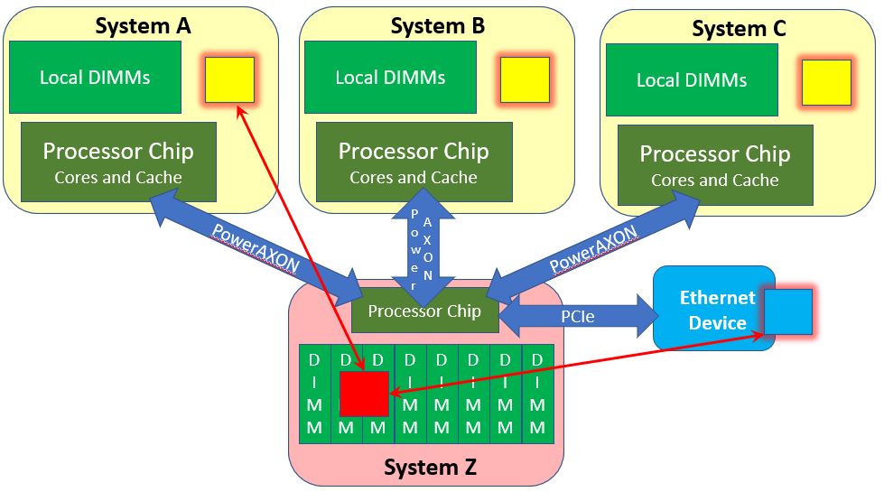
But, you need to keep the following in mind. Systems A, B, and C might all also hold that data block owned by System Z in their cache. But if that block in System Z gets changed in any manner – say via an I/O DMA into System Z’s DRAM or a core in System Z changing it, Systems A, B, and C would be unaware of this change.
It is not a cache-coherent SMP, and you needed to see just where it was not. But it is also the nearest thing to it. In many ways it does maintain the same semantics as an SMP. For a lot of stuff this really can be treated as a massive single system. But these few differences mean that you cannot just ignore the existence of the cache when determining how to use Memory Inception.
With that said, perhaps you would like to see some related words from William Starke, IBM distinguished engineer and a Power10 architect:
“When a memory request issues within that system (A), it coherently checks all caches in system (A). If the request is not satisfied from a cache, it gets satisfied by the memory home agents. If it gets satisfied by system (A’s) locally attached memory, the data is delivered from/to that memory, but any cached copies in other systems (B, C, D, …) are not queried or invalidated, so coherence is not maintained by hardware across the systems (if it were, we would not be calling this memory clustering, we’d be calling it a really big single SMP system). If the request gets satisfied by a memory home agent in system (A) associated with another system’s (B) memory, the request gets routed to that system (B) where it comes in as an I/O read or write. While the I/O read or write is coherently managed within that other system (B), once again any cached copies on other systems (C, D, …) are not queried or invalidated, so coherence is not maintained by hardware across the systems. Additionally, when an I/O read in system (B) sends data back to satisfy a load request in system (A), and that data is subsequently cached in system (A), there is no ‘check-out’ state logged in system (B) to provide an indication that system (A) holds the cache line. Once again, in this regard, coherence is not maintained by hardware across the systems. The net: this is not implementing a hardware coherent huge SMP. It is implementing a cluster-wide shared memory pool that is either restricted by system software to be used by only one system at a time, or it is managed by software to enable shared reader/writer structures across systems for communication.”
Yup, I don’t blame you for still being a tad confused. Memory Inception is not a full-blown SMP, but it is certainly also not shared-nothing networked systems. If you want to put it on a spectrum, largely because of its load/store accessibility of what would be remote memory, it is closer to the SMP end. Whatever it is, it is something wonderfully new to include in your system’s architecture plans. Perhaps then, at this point, it is best just to step back and get into your head where it is natural to use.
So, What Can You Do With It?
Massive Memory: Addressability to up to 2 PB of memory. A lot. And you are – for whatever reason – finding that a few score of terabytes of DRAM is still not enough. You have scads of compute power available to you even today in your SMP, but the constant paging of memory to/from even you flash storage is just not allowing you to use it. You’d like to quadruple it to – say – keep that massive database of your in memory.
Before going on, let’s recall that – aside from processing cores – there is a lot on these Power10 chips, memory controllers, SMP links, IO busses, cores/caches, to name a few. You, though, don’t need much, if any, additional compute capacity. If not needed, what does virtualization or energy management do with them? It shuts them down. Suddenly the “processor” chip becomes just a link to memory and I/O space.
So, you want to quadruple DRAM? Ideally, you could map all of it under the real address space of the system containing your compute capacity. It is all being accessed by the cores of your cache-coherent SMP, so inter-core cache coherency is not an issue. You are not sharing this extended memory, only accessing it from a single SMP. That does not say that the other cores are not being used, they are instead essentially unaware of the memory; the memory is owned in the virtual partition sense instead by an OS that happens to reside on a totally different SMP.
Notice this extension to virtualization? Virtualized memory, normally the partitioning of memory from within some given single SMP amongst multiple OSes, now also includes an OS owning portions of memory which reside on different SMPs, all being part of a memory cluster. You need more memory? Ask for it.
Inter-Process Communications: Your Process has some data that you want to send to another Process in another system. Basic communications, probably TCP/IP based. What do you do today? You shove it into a buffer, flush it down the communications stack, ultimately copying it between systems over the network, then working up the communications stack on the target system, ultimately to a buffer picked up by the target process. Works great, if not always entirely securely. Really, though, from your point of view, all you – your Process – is doing is providing your data to the target Process. It’s Inter-Process Communications. Once you say “deliver it”, you don’t ultimately care how it gets done, but ideally quickly, reliably, and securely.
So, here we are talking about a set of clustered systems. Process A is on System A and it wants to quickly communicate with a Process B on System B, quickly handshaking back and forth. In fact, from your point of view, let’s stick with exactly the same semantics as you would use for any networked system. But, being part of a Power 10 memory cluster, the underlying networking support decides to use that capability rather than more traditional networking. So, what do they set up? At the time you create a connection it sets up two buffers, one on System A, one on System B and then sets up cross system addressing as we saw above. You, on System A say as before write my data and your data gets copied by your core into System A’s local Buffer A. When you decide to actually “send it”, System A tells System B that data on this connection is available in Buffer A, doing so via an interrupt. A core on System B, knowing of the Buffer A from its point of view, merely arranges using its own core for Buffer A’s contents to be copied to Process B to memory owned by Process B. Process B responds to Process A using its own local Buffer B from which System A reads the response. Back and forth. And, BTW, once the data is copied out, the system merely invalidates its local cache of Buffer A or B, allowing the next use of that very same buffer.
That was all to avoid having your code be aware of Memory Inception. You thereby kept normal networking semantics. Next, to speed it further, let’s have your cross-system application use a complex data structure – an object if you like – which is Memory Inception aware. Still Buffers A and B, but now they are a form of heap space. Process A builds its data structure in local Buffer A, Process B consumes them from exactly there when available. Process B builds it data structure into Buffer B with Process A consuming it from there. (Be careful, though, here. Independent of Memory Inception, we are talking about sharing these data structures across Processes. Keep in mind that often times objects, like linked lists for example, contain Effective Addresses. The objects are process-local and those Effective Addresses have meaning only to the source process; Process A’s process-local Effective Addresses have meaning only to Process A, not Process B. Instead, since you are sharing this object across Processes, a form of addressing which can be understood by both Processes is needed.) But even a one-buffer scheme is possible as long as only one Process is the producer at a time. Again, this is because of the cache. As long as the data structure is flushed or invalidated from the cache(s) at the right time, the other process can see the changes.
There is a variation on this previous point and that relates to the notion of a file. Every file has some organization understood by any program accessing that file. The file is a complex data structure, typically one which is later forced to reside in persistent storage, a concept which brings us to the next point.
On The Subject Of Persistent Memory
Power10’s chip design includes what amounts to a generic interface – called Open Memory Interface (OMI) – to memory devices. As with PowerAXON, OMI supports 32 GT/sec with total chip bandwidth of 1 TB/sec. This can support DIMMs for DDR4, DDR5, GDDR, and Persistent Memory (a.k.a., Storage Class) DIMMs. It’s this last that is the subject of this section. And, again, you might want to refer back to HPE’s “The Machine.”
So, what are we talking about? A processor chip, supporting a fast interface to a memory device, here holding DIMMs which happen to hold data persistently. Unlike DRAM, which loses data held there when power goes off, persistent memory’s [1][2] data persists there. It’s a bit like a flash drive, but rather than an I/O-attached device, this is right next to the processor chip – and better – addressable in the same way as DRAM. It really is memory, but a power loss leaves the contents unchanged.
Or picture it like this, perhaps you have network-attached storage in your system. It’s another device, a device with processors and memory, which handle the storage of your data to persistent storage, and, of course, the subsequent reading from there. You communicate to that separate system via some form of networking. Aside from cost and speed, does it really matter to you how that device holds your data? Suppose that networked device used some form of persistent memory to most quickly make your data persistent, later writing it to a slower form of storage.
You now know that you can bypass the networking hardware. With you on System 1, that other system (System 2, owning the persistent storage) can be part of your memory cluster. And where is this persistent storage in System 2? It’s persistent memory, attached directly to System 2’s processor chips. That system can copy data directly into your memory and you can copy data directly into its memory. Perhaps we are talking about DRAM to DRAM copying but recall that the persistent memory – in the following called PRAM – also resides in the Real Address space of System 2, meaning that parts of it could also reside in System 1’s Real Address space.
As examples, …
- System 2 could be a Database Management system with the persistent form of the database typically residing within Persistent Memory (here called PRAM) with memory used for transactions held within the DRAM. System 1 is communicating with this DBMS by way of clustered memory, transaction requests in, result sets out. How does any DBMS make its changes to the database proper persist? Today a flattens its data and writes to a file, flushing it to – say – a disk drive. With persistent memory (PRAM) accessible from its processors, it copies its changes – using the cores and their caches – directly into via its own Real Address. Since a database transaction is not complete until the DBMS knows that some representation of the transaction is in persistent storage – and dependent transactions must wait until preceding transactions are complete – knowing more rapidly of this persistence also means higher throughput for the DBMS.
- System 2 is acting merely as though it were an External DASD device, a separate system in its own right. But here, System 1 is aware of the PRAM and has mapped part of it – say a particular file – into System 1’s Real Address space. (A notion like this is supported even today and is called a Memory-mapped File, but persistence requires that copy of the file in DRAM to later be flushed into Persistent Storage.) In the above, this memory-mapped file really is the persistent version of that file. No subsequent flushing is required and no associated delay is required.
Get the idea? This has rearchitected the notion of a system that we have had for decades, pulling the assurance of data persistence out of I/O space and into Real Address space makes it much closer to the processor producing and/or consuming the data. Shortening up this latency to very nearly memory speeds keeps work on the processors, not waiting for I/O devices to complete their work. As you have seen, it is not really all that different than what has been around for quite a while, but this new wrinkle has the potential of very considerably changing how we design and use systems.
Addendum
And, finally, a quick addendum. IBM calls all this “Memory Inception.” Based on the definitions, my suspicion is that someone at IBM has a keen sense of humor …
“3 (in science fiction) the act of instilling an idea into someone’s mind by entering his or her dreams.”
In Power10’s context, this would mean copying a new concept – a complex data object – into the memory of another system. I approve.

The Financial Longevity That Red Hat Gives IBM
It is hard to imagine, but someday, IBM may not care much about its proprietary System z and Power Systems platforms. Or, more precisely, it may not be able to afford to care the way it has for decades But the good news for Big Blue is that it has …

Google Gives A Peek At What A Quantum Computer Can Do
Four years ago, Google engineers boasted of achieving “quantum supremacy” following experiments that showed its 53-qubit Sycamore quantum system solving problems that classical supercomputers either can’t or take a very long time to accomplish. At the time, Google was slapped around by rivals in the quantum space, with competitors like …
Rest In Pieces: Servers And CXL
If you had to rank the level of hype around specific datacenter technologies, the top thing these days would be, without question, generative AI, probably followed by AI training and inference of all kinds and mixed precision computing in general. Co-packaged optics for both interconnects and I/O comes up a …
It would be nice, as future analysis, to see how the IBM memory inception architecture fits with modern Fortran’s notion of a coarray. Will there be compilers that support this in a natural way at launch?
The concept sends existing neural network frameworks straight to dust … everything in memory, hybrid connected hardware pushing this to there. Intel DPC++ is not far, C++ 20 closer with programs running solely in compiler.
Your comment is exact, ML and AI automated in compiler for unsupervised ML … getting closer to Star Trek.
It reads like getting RDMA under the hood (or adding an ‘RDMA accelerator’) bind with smoothing out some complex for new engineers to grasp network programming and process synchronization (programming) tasks. Not a small feat by all means
Interesting observation. I’ve been picturing quite a few higher level comm architectures – along with variations on inter-process shared-memory architectures – built on top of something like this. But I also wonder at what level and how different. For example, with RDMA, even for simplex communications, there is still a source buffer and a target buffer, each securely addressed in each system. It strikes me that RDMA assumes exactly that (but would be pleased to learn otherwise). In RDMA, each system provides linkage into their system’s memory windows and all of the associated lower-level enablement and seems to show that to the RDMA user. This clustered memory, though, the simplex communications seems to be built upon a single shared memory buffer. Both systems and processes on each know of that one shared buffer. The lower-level enablement sets things up so that the two systems and these processes see the same thing using their own higher-level addresses, again allowing cores on both systems to access the share buffer. I’m just not sure that this underlying difference can be hidden from the RDMA user. Move it up a level, though, as in “I want that other system to see my data” then sure.
This is all really impressive. Is it substantively different from the Cray X1 or SGI origin of 20 years ago? Obviously there’s a lot more bytes and more bytes per second.
One major difference is the advent of in-memory computation which is also pioneered at IBM labs: https://www.zurich.ibm.com/sto/memory/
Considering the memory attached to the Power10 cores could be not just DRAM, but also compute-capable PCRAM with neural processing embedded into the PCRAM matrix, it’d make sense for several cores to be able to access that portion of memory in a shared way. Maybe another good reason to call it “memory inception”?
I kept expecting to see an explanation for how this architecture differs from NUMA (Non-Uniform Memory Access) or the Kendall Square Research (KSR-1) machine’s “All Cache Memory” architecture.
Right. NUMA (Non-Uniform Memory Access) is a characteristic of pretty much any multi-socket SMP-based system. Such a cache-coherent SMP system is also called ccNUMA. Its non-uniform in the sense that a core’s access of the memory hung off of its own socket tends to be faster than an identical access from memory hung off of another socket. NUMA, then, is a performance issue, not a functional issue. As long as a core can directly access memory in a cache coherent manner, it is an SMP; again, a functional issue. I had considered folding NUMA into this article, but it was getting quite long as it was and for now wanted to stick with the functional aspects of it. But as a hopefully straightforward answer, notice that IBM’s PowerAXON is being used for cross-socket accesses within their (NUMA) SMPs, even for up to their 16-socket system. Now also notice that PowerAXON is being used for clustered memory as well.
It’s been so long ago I don’t trust my memory, but didn’t the KSR approach require operating system support? I seem to remember it being “page faulting over the network instead of to disk”. That’s a gross oversimplification and there must have been some elegant locking. I saw a KSR-1, once. Running. 🙂